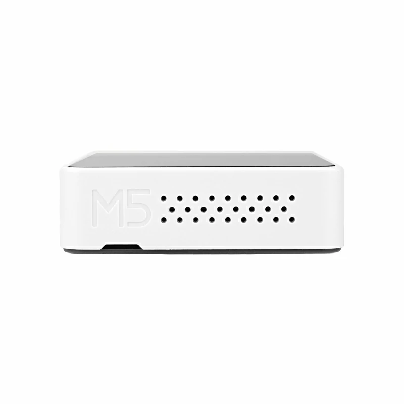
Core2 v1.1
Description
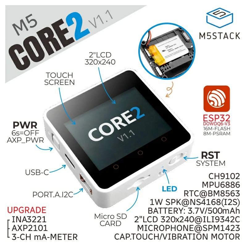
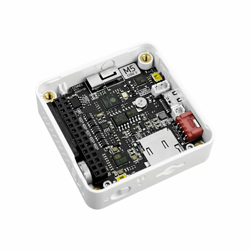
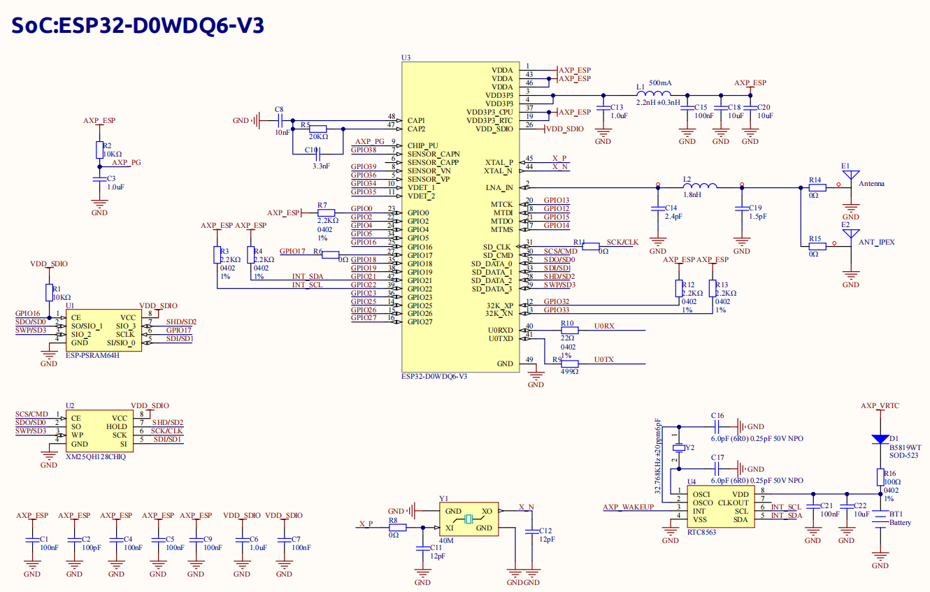
Core2 V1.1 is an iterative version of Core, with upgraded power IC and a continuation of the classic design of Core2. It is a powerful and user-friendly development board. Core2 V1.1 is equipped with ESP32-D0WDQ6-V3, featuring two independent Xtensa® 32-bit LX6 processors with a clock frequency of up to 240MHz. It supports WiFi functionality and has onboard 16MB Flash and 8MB PSRAM, and supports program downloading via the TYPE-C interface. Its strong configuration can meet the requirements of complex applications.
Core2 V1.1 is equipped with a 2.0-inch integrated capacitive touch screen. The three dots on the front of the screen are part of the touch screen. Users can set the hot zone mapping as three virtual buttons through programming, enabling diverse human-machine interaction experiences. Additionally, Core2 V1.1 has a built-in vibration motor for haptic feedback and vibration alert functionality.
Core2 V1.1 has an integrated RTC module and a dedicated battery for RTC power supply, providing accurate timing functionality. Furthermore, the AXP2101 power management chip effectively controls the power consumption of the device. Core2 V1.1 also has a built-in blue power indicator light, which can be used to implement specific functions or status indications according to the user's application needs. Core2 V1.1 is also equipped with a MicroSD card slot, speaker, and a high-quality I2S digital audio interface power amplifier chip. The expansion board on the back of the device integrates a 6-axis IMU sensor and a microphone, providing additional functionality and possibilities.
The differences between Core2 and Core2 v1.1 are as follows:
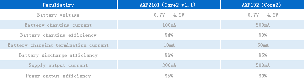
1.The power management scheme is iterated from Core2(AXP192) to Core2 v1.1(AXP2101+INA3221). The ID of AXP192 and AXP2101 is different, and the program uses this as a sign to distinguish the versions;
2.The power indicator is changed from green to blue;
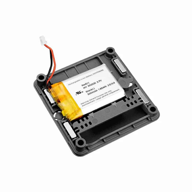
3.Add RTC chip power supply battery to ensure accurate timing when power is off.
Power Management
Operations:
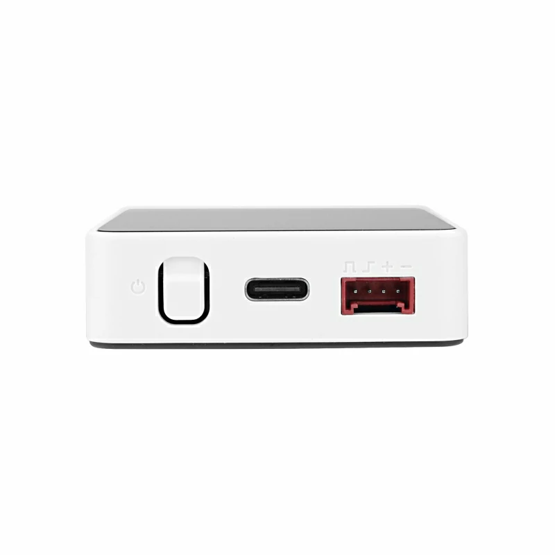
Power on: One click the power button on the left
Power off: Long press the left power button for 6 seconds
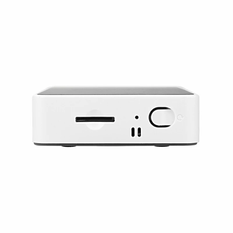
Reset: Click the RST button on the bottom side
USB drive
Before using, please go to
download page
to download the USB driver that matches your operating system, and install it.
Note: Core2 currently has two CH9102F A USB chip version, users can install the drivers (CH9102) that are compatible with two ICs at the same time to ensure that the device drivers work normally.
Extensions
To stack Core2 V1.1 with M5 modules, you need to remove/eliminate the battery bottom of Core2 V1.1; If you wish to keep I2S Mic, IMU and Battery functions, a M5GO Bottom2 is required.
The vibration sensor of Core2 V1.1 and M5 Base series are incompatible in mechanical design. Please do not stack them together.
Some of the screen edges will have touch non-linearity problem, you can try to use M5Tool to upgrade the screen firmware to solve this problem.
This product contains batteries that are non-replaceable.
Tutorial


Features
- ESP32-based, built-in Wi-Fi
- 16M Flash,8M PSRAM
- Built-in speaker, power indicator, vibration motor, RTC, I2S amplifier, capacitive touch screen, power button, reset button
- TF card slot (16G Maximum size)
- Built-in lithium battery, equipped with power management chip
- Independent small board built-in 6-axis IMU, PDM microphone
- M-Bus Socket & Pins
- Compatible with multi-platform development:
- UIFlow
- MicroPython
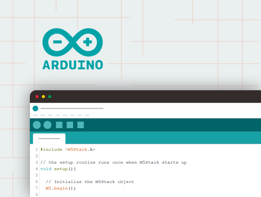
- Arduino
- .NET nanoFramework
- Operating System (RTOS):zephyr
Includes
- 1x Core2 V1.1
- 1x Type-C USB(20cm)
- 1x HEX KEY
Applications
- Internet of things terminal controller
- Stem education product
- DIY creation
- Smart home equipment
Specification
| Resources | Parameters |
|---|---|
| ESP32-D0WDQ6-V3 | 240MHz dual core, 600 DMIPS, 520KB SRAM, Wi-Fi |
| Flash | 16MB |
| PSRAM | 8MB |
| Input Voltage | 5V @ 500mA |
| Interface | TypeC x 1, GROVE(I2C+I/0+UART) x 1 |
| IPS LCD Screen | 2.0"@320*240 ILI9342C |
| Touch Screen | FT6336U |
| Speaker | 1W(SIZE:0928) |
| LED | Green power indicator light |
| Button | Power button, RST button, Virtual screen button*3 |
| Vibration reminder | Vibration motor |
| MIC | SPM1423 |
| I2S Power Amplifier | NS4168 |
| 6-axis IMU | MPU6886 |
| RTC | BM8563 |
| PMU | AXP2101 |
| Current Meter | INA3221 |
| USB Chip | CH9102F |
| DC-DC Boost | SY7088 |
| TF card slot | 16G Max |
| Lithium Battery | 500mAh @ 3.7V |
| Antenna | 2.4G 3D antenna |
| Operating temperature | 0°C to 60°C |
| Base screw specifications | Hexagon socket countersunk head M3 |
| Internal PCB board reserved interface | Battery interface (specification: 1.25mm-2P) USB line interface (specification: 1.25mm-4P) |
| Case Material | Plastic ( PC ) |
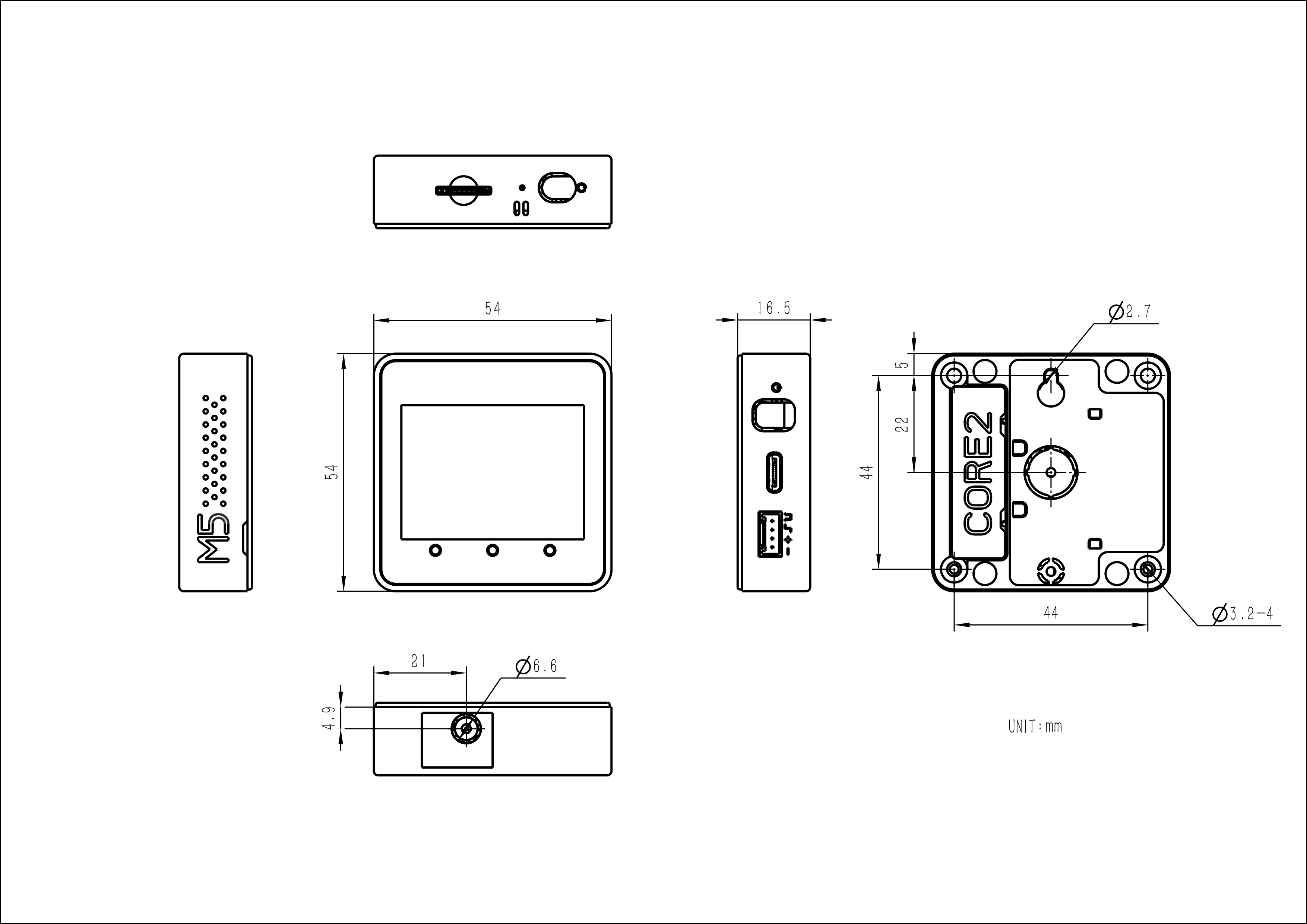
| Product Size | 54 x 54 x 16.5mm |
| Package Size | 75 x 60 x 20mm |
| Product Weight | 54.8g |
| Package Weight | 83.9g |
Products related to this item
Stepmotor Driver Module13.2 v1.1 (M039-V11)
Related Link
Schematic
EasyLoader
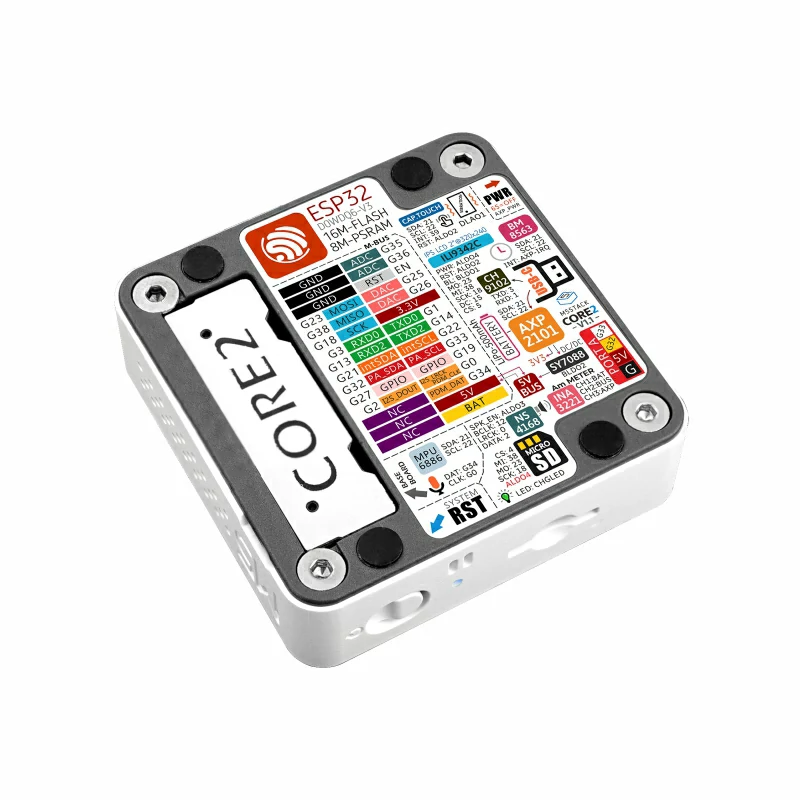
PinMap
LCD & TF card(LCD :320x240 TF card Maximum size 16GB)
| ESP32 Chip | GPIO38 | GPIO23 | GPIO18 | GPIO5 | GPIO15 | |||
|---|---|---|---|---|---|---|---|---|
| AXP2101 Chip | AXP_ALDO2 | AXP_BLDO1 | AXP_ALDO4 | |||||
| ILI9342C | MISO | MOSI | SCK | CS | DC | RST | BL | PWR |
| ESP32 Chip | GPIO38 | GPIO23 | GPIO18 | GPIO4 |
|---|---|---|---|---|
| TF Card | MISO | MOSI | SCK | CS |
CAP.TOUCH (I2C Addr: 0x38)
| ESP32 chip | GPIO21 | GPIO22 | GPIO39 | |
|---|---|---|---|---|
| AXP2101 | AXP_ALDO2 | |||
| FT6336U | SDA | SCL | INT | RST |
Mic & NS4168(Speaker)
| ESP32 Chip | GPIO12 | GPIO0 | GPIO2 | AXP_ALDO3 | GPIO34 |
|---|---|---|---|---|---|
| NS4168 | BCLK | LRCK | DATA | SPK_EN | |
| Mic | CLK | DATA |
AXP Power Indicator Light
| AXP2101 | VRTC | DLDO1 |
|---|---|---|
| Bule LED | Vcc | |
| Vibration motor | Vcc |
RTC
| ESP32 Chip | GPIO21 | GPIO22 | |
|---|---|---|---|
| AXP2101 | AXP_IRQ | ||
| BM8563 | SDA | SCL | INT |
IMU(3-axis gyroscope & 3-axis accelerometer)
| ESP32 Chip | GPIO21 | GPIO22 |
|---|---|---|
| MPU6886 | SDA | SCL |
USB to serial chip
| ESP32 Chip | GPIO1 | GPIO3 |
|---|---|---|
| CH9102F | RXD | TXD |
Internal I2C connection
| ESP32 Chip | GPIO21 | GPIO22 |
|---|---|---|
| MPU6886 | SDA | SCL |
| AXP2101 | SDA | SCL |
| BM8563 | SDA | SCL |
| FT6336U | SDA | SCL |
| INA3221 | SDA | SCL |
M5PORT DEFINE
| PORT | PIN | NOTE: |
|---|---|---|
| PORT-A(Red) | G32/33 | I2C |
| PORT-B(Black) | G26/36 | DAC/ADC |
| PORT-C(Bule) | G13/14 | UART |
ESP32 ADC/DAC(For more information about Pin assignment and Pin Remapping, Please refer to ESP32 Datasheet )
| ADC1 | ADC2 | DAC1 | DAC2 |
|---|---|---|---|
| 8 Channels | 10 Channels | 2 Channels | 2 Channels |
| G32-39 | G0/2/4/12-15/25-27 | G25 | G26 |
Core2 v1.1 M-BUS Schematic diagram
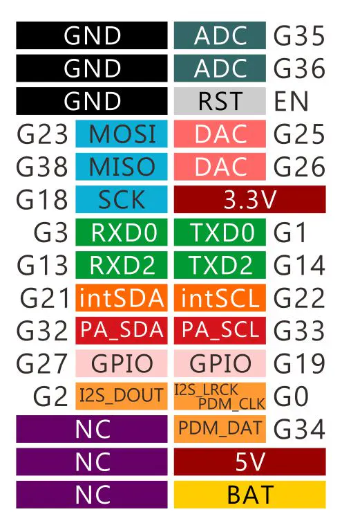
Core2 v1.1 BUS(compared to M5Stack)

Module Size
Examples
Arduino
Video
- This case will perform hardware running tests for speakers, wifi, buttons, accelerometer, TF-card(microSD), screen, etc.
Version Change
| Release Date | Product Changes | Notes |
|---|---|---|
| / | First ReleaseCore2 | / |
| 2023.11 | Core2 v1.1 | Change PMU power management chip to AXP2101+INA3221/ Add RTC power battery/The power indicator changes to blue |
Comparison of AXP2101(Core2 v1.1) and AXP192(Core2) parameters
FAQ
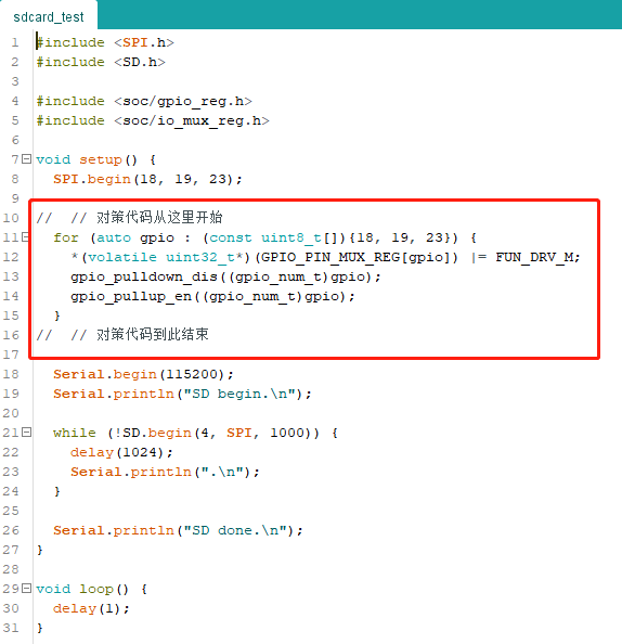
Q: If the memory card fails to read, you can add the following code in the initialization to increase the host memory card reading ability.
A:
for (auto gpio : (const uint8_t[]){18, 19, 23}) {
    *(volatile uint32_t*)(GPIO_PIN_MUX_REG[gpio]) |= FUN_DRV_M;
    gpio_pulldown_dis((gpio_num_t)gpio);
    gpio_pullup_en((gpio_num_t)gpio);
  }